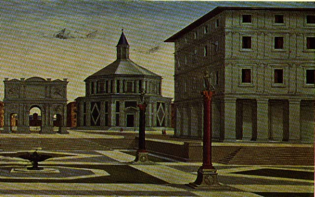
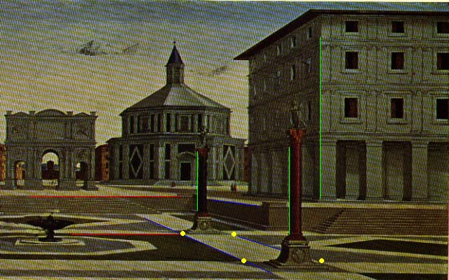
We use Robert Collins' method to calculate vanishing points. For each X, Y and Z direction, we choose two or more points to form a line in that direction by sovling the least square problem. Considering the numerical condition, we translated the coordinates by (-image_width/2, -image_height/2), and also scaled the coordinates so that the magnitude of all image point homogeneous coordinates is roughly 1 by taking the w to be the average of the sum of the image height and width.
If there are only two lines in the direction, we just took the cross-product of the two lines to get the vanishing point.
If more than two lines are involved, we get the "best_fit" vanishing point as follows:
a) form the 3x3 "second moment" matrix M as
[ a_i*a_i a_i*b_i a_i*c_i ]
M = sum [ a_i*b_i b_i*b*i b_i*c_i ]
[ a_i*c_i b_i*c_i c_i*c_i ]
where the sum is taken for i = 1 to n. Note that M is a symmetric matrix
b) perform an eigendecomposition of M, using the Jacobi method, from numerical recipes in C.
c) the eigenvector associated with the smallest eigenvalue is the vanishing point vector V.
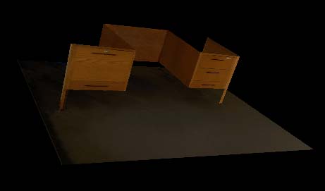
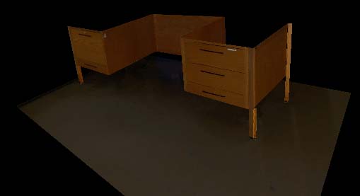
We chose 4 points on the reference plane, which is the floor, to get the homography M from reference plane to the image. To do the measurement within the reference plane, for each image point (u,v) of the reference plane, we calculate its 3D position by applying M_inverse*(u,v)_transpose. To do the measurement within the plane which is parallel with the reference plane, we first mapping the image points on the parallel plane onto the points on the reference plane by applying the homology matrix H-tilta, which can be formed by the formula given in the paper, then apply the M_inverse.
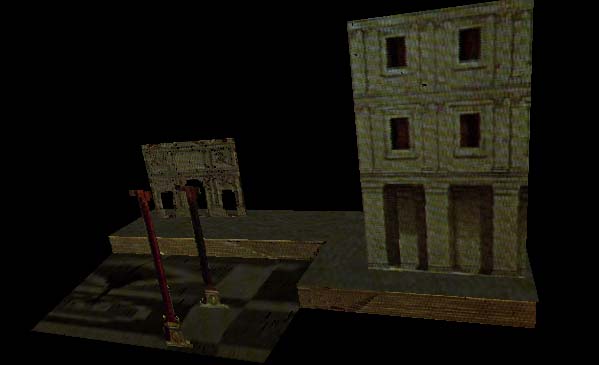
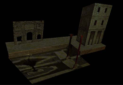
We use the points we have measured to define several planar patches in the scene. If the patch is a rectangle in the scene, we just warp the quadrialateral image region into a rectangular texture images. If the patch is a non_rectanglar region as the polar patch shown above, we first define a quadrilateral in the image containing the region, then warp it into a rectangulat texture image, and last edit the texture image and mark out transparent pixels by hand using PhotoShop.