|
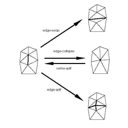
| Figure 1. Basic operations for transforming elements of a triangle mesh. |
Michael MCGuffin
University of Toronto
June 2001
A course project completed for CSC 2505: Geometric Representations for Computer Graphics (Prof. Alejo Hausner)
Surfaces can be modelled with a variety of techniques, including polygonal meshes, splines, implicit representations, and particle systems. Of these, polygonal meshes are the simplest technique, supported by almost every hardware renderer, and serve as a lowest common denominator for modelling systems. Despite the inability of polygonal meshes to accurately model curved surfaces, and the growing popularity of spline techniques, polygonal modelling remains important and widely used in industry.
Editing a polygonal mesh can be painfully slow if done by transforming individual vertices, edges, or faces. One of the first techniques [1] proposed for direct manipulation of polygonal meshes involves specifying operations (such as translation of vertices) over a range of influence. Essentially, a subset of mesh elements is selected, and the effect of subsequent operations performed on the elements is attenuated according to some decay function. The decay function determines the shape of a virtual brush, and can be varied to achieve effects such as "soft" or "hard" selections.
Some modelling systems [9] support the "painterly" application of soft brushes for editing spline surfaces. The user can click and drag over a region to create positive or negative indentations in the surface. Dragging repeatedly over one region increases the effect incrementally. This is not unlike how the colour left by an airbrush becomes gradually stronger as the artist lingers over one spot on a canvas.
Interactive sculpting of this type can be done with polygonal meshes as well (figure 2b). However, as the mesh is stretched out during the sculpting process, the density of the mesh decreases, and thus the user gradually has less and less granularity to shape and mould with. Although the user could simply subdivide the mesh to any desired level, this interrupts the modelling process, and is unfaithful to the metaphor of true sculpting.
This paper considers techniques for automatic, localized subdivision of the mesh as it is sculpted, to make the user's workflow smoother. To the author's knowledge, no schemes for this have been proposed for polygonal meshes in the context of interactive sculpting.
At the same time, this paper also explores the use of a bimanual interface for performing the sculpting. Bimanual (or two-handed) input can allow users to perform complex tasks involving many degrees of freedom more fluidly than with one device. Previous research has described new interaction techniques [13] and demonstrated improved performance [2] using bimanual interfaces for 3D tasks. Despite this, bimanual interfaces remain uncommon, especially in commercial software packages.
This paper describes different uses of a bimanual interface for simultaneous control of brush strokes, brush size, or camera view. Together with a scheme for automatic subdivision, the author hopes to create a system where sculpting of polygonal meshes can be done in a fluid manner.
Following is a brief review of some relevant background work. Next, some alternate design approaches are considered. In the Implementation section, details of the scultping algorithm are given, and some unexpected problems that were encountered during development are described. Finally, results of the research are presented, as well as possible directions for future research.
Welch and Witkin [12] describe a free-form shape design technique for variational surfaces. Variational surfaces are produced by fitting a smooth surface between "character lines" that pin down and outline the shape of a surface. Welch and Witkin triangulate these surfaces to generate a mesh, which is automatically refined or re-triangulated as needed. (Note, however, that in their scheme, they "do not require the surface to respond in an intuitive or natural way to direct control-point manipulation".) In their paper, 3 basic operations are used to transform the mesh: edge-swap, edge-split, and edge-collapse (figure 1).
Hoppe et al. [6] proved that the edge-collapse and edge-split operations are sufficient to transform any surface triangulation into another of the same topological type. More recently, Hoppe [7] introduced the vertex-split operation (figure 1), which is the inverse of an edge-collapse. Collectively, the 4 operations in figure 1 can be used for refinement, un-refinement, or for eliminating skinny triangles.
Turning to bimanual interaction, Guird [5] established the Kinematic Chain (KC) model of skilled bimanual action, whence three principles emerge. First, the non-dominant hand (NDH) sets the frame of reference relative to which the dominant hand (DH) performs its actions. Second, motion of the NDH is coarser and less frequent than that of the DH. Third, motion of the NDH usually precedes that of the DH.
Various interfaces have been described [4,13,2] that exploit dual streams of continuous input, many of which can be rationalized using the KC model. For example, Bier et al. [4] propose using the NDH to position a see-through tool palette that the DH can click through and onto a canvas, thereby selecting a tool and activating it all at once. In this way, the NDH sets the frame or reference for action with the DH.
Balakrishnan [2] studied the use of the NDH to perform camera control in a 3D scene, while the DH is used to manipulate the scene. By moving the camera with the NDH, the user can gain motion depth cues to improve their perception of the scene. The user can thus perform epistemic actions (that facilitate perception and cognition) with the NDH, and pragmatic actions (that achieve physical goals) with the DH simultaneously.
LeBlanc et al. [8] describe a bimanual system for sculpting surfaces, however, the sculpting cannot be done in a "painterly" fasion akin to brush strokes. Rather, groups of vertices are selected and then displaced with the DH according to some decay function much as Allan et al. proposed [1]. Meanwhile, the NDH controls the camera view, allowing the user to perceive enriched "motion parallax" depth cues. Their system has no support for automated mesh subdivision during sculpting.
|
|
| Figure 1. Basic operations for transforming elements of a triangle mesh. |
Sculpting
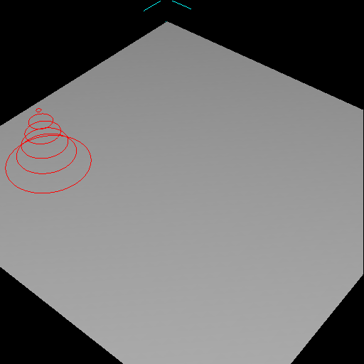
The sculpting brush creates elevations or indentations of a given shape in the polygonal mesh. To support painterly application of the brush, the user should be able to click and drag a pointing device, creating a ridge or valley in the mesh (figure 2b). If, during a single click-drag, the stroke passes over a point more than once, one might expect the effect over that point to be increased (as though the user were painting with an airbrush). This situation is illustrated in figure 2d. However, another possibilty is to have the elevation of the brush stroke saturate, as in figure 2c.
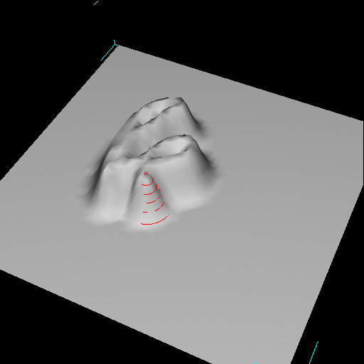
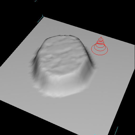
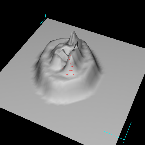
The behaviour in figure 2c is expected to provide more control over the sculpting process, and was chosen for the implemented system. Since the elevation is clamped according to the height of the brush, the user may drag out closed curves (such as circles, to model the contour of a crater), or drag repeatedly over one region with predictable results (figure 3a, 3b). To build on top of an elevation in an incremental manner, the user must release and click again, starting a new stroke (figure 3c). In this way, incremental building of a form layer-by-layer is still allowed, however the layering is done over many brush strokes rather than during a single stroke.
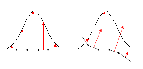
In keeping with the brush metaphor, the displacement vector applied to each mesh element is proportional to the amplitude of the brush over the element. However, because the displacement should saturate if the user drags repeatedly over one region, the direction of each displacement vector should be independant of the brush's position. For simplicity, it was decided that the brush -- as displayed on screen -- would always be aligned with the normal at the brush's centre. However, the displacement vectors, rather than being parallel to the direction of the brush, are aligned with the normal at each mesh element (figure 4).
Subdivision Schemes
To prevent triangles from getting too large as they are sculpted, an automatic, localized subdivision scheme is required. For simplicity, the modelling system is limited to supporting triangle meshes. Hence, the subdivision scheme must not generate any polygons other than triangles. Furthermore, the scheme should ideally not generate cracks (i.e. T-vertices) or thin triangles.
Figures 5, 6, and 7 illustrate 3 potential subdivision schemes. It is assumed that, as input, the subdivision algorithm is given a list of triangles to subdivide. The triangles could be chosen according to some heuristic rule, e.g. if their area exceeds some threshold. The scheme in figure 5 produces cracks and is therefore undesirable. Figure 6 illustrates an acceptable scheme, however almost certainly not as good as that in figure 7, where the only thin triangles produced are in the neighbourhood of the triangles to subdivide. (As seen in figure 8, however, this scheme must be carefully implemented to properly detect and subdivide all necessary neighbouring faces.)
To further reduce thin triangles, the schemes in figures 6 and 7 could be followed by an additional pass where edge-swaps are performed.
Bimanual Interface
Some of the parameters that a user may wish to control while scuplting are the brush's position on the mesh, the brush's size (i.e. radius and amplitude), and the camera view. Each of these can be controlled with a 2D pointing device. Following the example of [2], a natural bimanual interface would allow control over the brush's position with the DH, and simultaneous control over the camera view (e.g. via orbiting) with the NDH. It is also expected that simultaneous control over the brush's position and size would be useful, hence the implemented interface allows the NDH to control either camera view or brush size, switching between the two with a mouse button.
The author also used the implemented system to test a bimanual interface for pure camera control [10]. Zeleznik [13] previously described two schemes for 2-handed camera control, however the author's scheme differs in that it mimicks a flying (or camera centric) metaphor, while still affording the possibility of orbiting around a point-of-interest.
|
| Figure 2a. The user places the brush, which has the shape of a bell curve, on an initially flat mesh. |
|
| Figure 2b. Clicking and dragging the brush sculpts the mesh by creating an elevated ridge. |
|
| Figure 2c. If a single stroke comes back on itself, rather than creating an elevation of twice the height at the intersection (as one might expect with an airbrush metaphor), the elevation simply saturates. |
|
| Figure 2d. A mock-up of what a single stroke might look like if strokes elevated the mesh incrementally rather than saturating. This behaviour would be akin to an airbrush. |
|
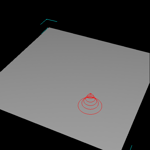
| Figure 3a. Because the elevation created by a single stroke saturates, the user can drag repeatedly over a single region to create a plateau. |
|
| Figure 3b. Once the plateau is complete, the user ends the stroke by releasing the mouse button. |
|
| Figure 3c. The user may now click and drag again, to build on top of the elevation created by the first stroke. |
|
| Figure 4. A gaussian brush, placed over some mesh elements, seen from the side. Arrows show the displacement that would result if the brush were applied. Displacement vectors are aligned with the normals at the mesh elements. On the left, the mesh is flat, and hence the displacement vectors all happen to be parallel to the direction of the brush. In general, however, this is not the case. On the right, the displacement vectors are not parallel to the direction of the brush. |

|
| Figure 5. On the left is a mesh where some (shaded) triangles have been chosen to be subdivided. On the right is the resulting mesh. Under this scheme, each triangle is split into 4 similar triangles, ensuring that the resulting triangles are no thinner than the initial triangles. Unfortunately, this introduces T-vertices that create discontinuities in the surface normals, and would quickly lead to cracks as the mesh is manipulated. |

|
| Figure 6. A mesh before and after subdivision. In this scheme, each triangle to be subdivided is split into three smaller triangles. Unfortunately, this introduces skinny triangles. |
|
| Figure 7. A better subdivision scheme, where triangles are split into similar triangles, and neighbouring triangles are split as necessary to eliminate T-vertices. Although the splitting of neighbours introduces skinny triangles, the problem is less severe than with the scheme in figure 6. |
|
| Figure 8. The subdivision scheme of figure 7, here applied to a case where the neigbourhood of triangles that are affected is rather large. |
The sculpting system was built on top of a simple 3D modeller framework written in C++. The framework supports triangle meshes. Multiple meshes can be created, selected, or transformed (e.g. translated, rotated, scaled) via 3D widgets.
Brush Strokes
Although many different decay functions are possible [1] to define the brush's shape, only a gaussian brush was implemented. Other shapes would be easy to add, and would not likely affect our evaluation of the subdivision scheme or the bimanual interface.
To initiate a brush stroke, the user must place the brush over a mesh M, and click and hold down a mouse button. When this happens, the system creates a copy M0 in memory of M (without displaying the copy), and also creates an array D of floating point values, whose size is equal to the number of vertices in the mesh, and whose values are initially all zero. The array D is used to store the lengths of displacement vectors.
After this first click, and for each mouse motion event thereafter, the following is done:
compute the set S of vertices in M0 covered by the brush
for each vertex v in S,compute the displacement distance d = decay_function ( distance ( v, brush_centre ) )redisplay M
D [ v ] = max ( D [ v ], d )
compute the normal n to M0 at v
let v' be the vertex in M corresponding to v
v' = v + D [ v ] * n
This continues until the user completes the stroke by releasing the mouse button, whereupon M0 and D are deleted.
Unfortunately, because the displacement vectors are aligned with surface normals (figure 4), sculpting with the brush can create self-intersections in the mesh. This happens, for example, when a tall brush is stroked past a concave crease in the mesh (figure 2d).
Subdivision
The only subdivision scheme implemented is the one depicted in figure 6. No edge swapping was attempted.
During brush strokes, following every change to the mesh, the modified triangles are tested to see if their area exceeds a threshold. If so, the subdivision scheme depicted in figure 6 is applied. Two problems were found with this scheme. First, the subdivision often introduced concavities in the mesh (figure 9). Although edge-swapping could alleviate this problem, it is not clear what heuristic to use to decide when to edge-swap. Edge-swaps should ideally produce a mesh curvature that "looks" correct, and that also increases acute angles.
Second, due to a subtle design problem with the implemented system, the program can be easily made to perform a runaway subdivision that creates faces of zero area and/or a large number of faces incident on a single vertex (both of which can cause the program to crash). The problem lies in the splitting of triangles: the position of each new vertex is sometimes poorly chosen, resulting in fatal side-effects.
Bimanual Interface
Each hand controls a 3-button mouse. The DH's mouse is read through the operating system's usual infrastructure (in this case, X11). The second mouse is connected to a serial port, from which raw bytes are read (through a UNIX file handle) and interpreted by the program. This is an inexpensive and simple way of obtaining input from 2 mice simultaneously.
Different combinations of mouse buttons and modifier keys allow the user to orbit, pan, or dolly the camera with either hand; perform brush strokes with the DH; and adjust the size (i.e. radius and amplitude) of the brush with the NDH.
Simultaneous brush stroking (with the DH) and adjustment of the brush size (with the NDH) allows the user to "paint" ridges or valleys that vary in width and/or height along the stroke (figure 10). Simultaneous brush stroking (with the DH) and camera orbiting (with the NDH) did not work well initially. Orbiting was done around a target point (typically the centre of the mesh), which meant that motion by the NDH usually destroyed the pick correlation of the DH's pointer. As a remedy, the orbiting function was modified to rotate the camera around the point being picked by the DH (e.g. the brush's centre).
An informal test was performed by the author to try and sculpt a face. Adjusting the brush's size during brush strokes proved critical for modelling forms such as a nose or brow. Adjustment of the brush size not only allows the user to change the shape of the ridge being created, but also gives fine control over how the base of the ridge blends with the surrounding mesh. In comparison, a 1-handed interface, even if multiplexed, would not be able to achieve the same degree of fine-grain, continuous control over both brush size and brush position.
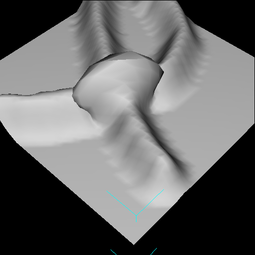
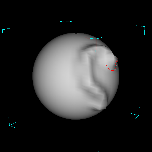
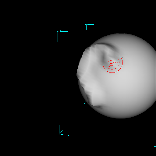
The ability to orbit without releasing a stroke was critical for performing strokes past the mesh's silhouette (figure 11). To perform the same sculpting with a 1-handed interface would require the user to apply 2 or more smaller strokes, which would be difficult to join or meld together continuously.
Finally, a special mode (activated with a hotkey) switches the user into bimanual camera control. The DH yaws and pitches the camera, while the NDH translates the camera parallel to the camera plane. Simultaneous motion by both hands in opposite directions caused the camera to orbit as predicted [10]. However, problems in reading the events from the NDH's mouse creating disturbing jitter in the orbiting motion. An averaging filter was implemented to make the data from the NDH's mouse smoother.
|
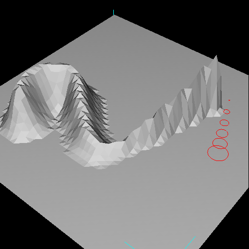
| Figure 9. The elevation created by a click-release with a gaussian shaped brush, seen from above and from the side. Large triangles were automatically subdivided. Although the elevation's silhouette should be bell-shaped, the subdivision introduced a vertex (indicated by the arrow) that creates a concavity in the mesh. Note that, in this case, a single edge-swap would eliminate the concavity. |
|
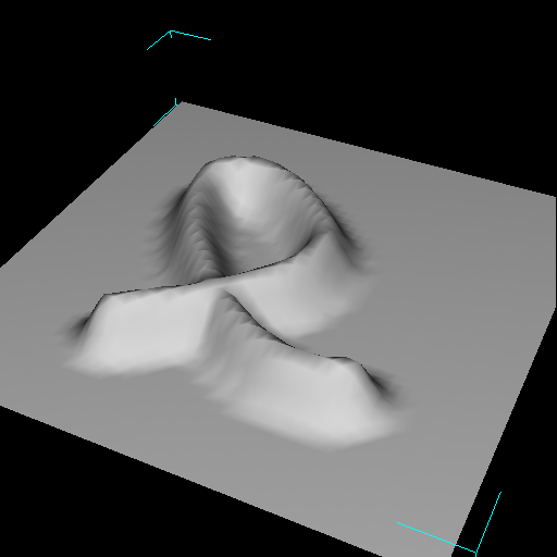
| Figure 10. Simultaneous control over the brush's position and size allows the user to create elevated ridges of varying height and/or width. |
|
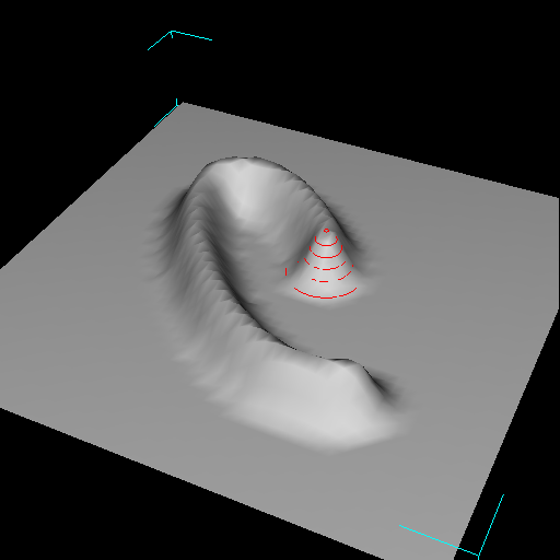
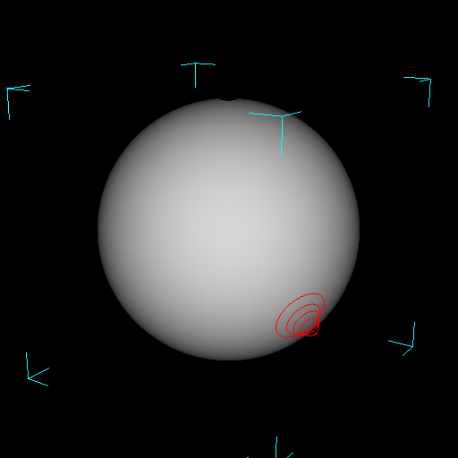
| Figure 11. A brush stroke that approaches, and must continue past, the silhouette of the mesh. As the user approaches the silhouette, the NDH is used to orbit the object. Notice how the DH's pick correlation is conserved between the 2nd and 3rd pictures. |
The sculpting brush works well under some circumstances, however it can cause interpenetrations in the mesh surface -- as when a brush stroke passes over a concave crease.
The subdivision scheme implemented is inadequate, as it produces undesirable concavities in the mesh and, in the form implemented here, suffers from design bugs.
Simultaneous control over the brush's position and the brush's size or camera view afford qualitatively improved control over the sculpting process. Furthermore, the bimanual camera navigation interface allows users to orbit around regions of space, varying the region-of-interest by changing the relative speed of their hand motion.
This paper has demonstrated the viability of a brush metaphor for sculpting triangle meshes. Although some important issues remain unaddressed, in particular how to automatically subdivide the mesh, the system implemented provides a (mostly) working example to build on. Furthermore, the results add to the growing body of evidence supporting the usefulness of bimanual interfaces. The bimanual camera navigation scheme, in particular, is promising as it integrates aspects of flying (or camera centric) metaphors with orbiting (or object centric) metaphors.
Future directions this work could take include exploring alternative brush schemes (such as an airbrush metaphor, as in figure 2d; or a "magnet" brush that attracts/repels mesh elements), better subdivision schemes (such as the one in figure 7 and/or a scheme incorporating edge swapping or other operations from figure 1), and alternative bimanual interfaces (such as using the NDH to control the direction of the brush, or even the shape of the brush -- perhaps using shape tape [3]).
Finally, sculpting metaphors similar to the one presented here will always be limited in that they preclude changes to surface topology. Alternative techniques that enable the user to perform cutting, stitching, and other "surgical" operations [12] also need to be explored and enhanced with new input schemes (such as bimanual interfaces).