Planning Stage:
A Tachometer is a device on a vehicle (typically a gauge) that tells you how quickly the crankshaft of the engine is turning (typically in a unit of measure called RPM - revolutions per minute.) The crankshaft is a bar attached to the pistons of the engine by connecting rods, and it is the force that the pistons exert on the crankshaft through the connecting rods that result in the output the engine produces. (Excellent material and an animation explaining the components of a four-stroke engine can be found here.)
The speed at which the crankshaft revolves is a fundamental source of input for this project. A direct way to obtain this input is to look at the "ignition system".
The ignition system of a vehicle does what the name implies: it is responsible for "igniting" the fuel - providing the spark that is responsible for combustion. (Excellent documentation and an animation explaining the concept can be found here.)
The ignition coil produces a high voltage current (the current needed to produce a spark) twice for every revolution of the crankshaft. This can be deduced from understanding the engine and how it works. The 22R-E (the engine in the vehicle) is a 4-cylinder, four-stroke internal combustion engine. "Four-stroke" means that the engine operates in the following way:
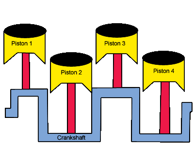
Since the engine has 4 cylinders, and the complete cycle of a cylinder in a four-stroke engine results in 720 degrees of revolution of the crankshaft (recalling that all pistons are connected to the crankshaft VIA connecting rods) each of the cylinders is "offset" by 180 degrees. The following diagram conveys this concept (note that the pistons and crankshaft may not be set up exactly in this configuration):
If Piston 1 has just completed its compression stroke, Piston 3 has just completed its exhaust stroke. If Piston 2 has just completed its combustion stroke, Piston 4 has just completed its intake stroke. In addition, the combustion stroke of one cylinder results in a 180 degree revolution of the crankshaft. Because of this, it takes combustion in two cylinders for one complete revolution of the crankshaft.
The approach is then to monitor the current produced by the ignition coil. The following electrical diagram shows a portion of the ignition system (coloured in black):
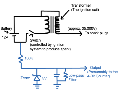
An introduction to Volts, Amps, and Ohms can be found here. The transformer in the diagram is the ignition coil (concise documentation on what transformers are and how they work can be found here). Its purpose in the ignition system is to create high voltage current. The high voltage is necessary for the current to "jump across" the contacts of the spark plug, producing the spark responsible for fuel combustion.
To obtain the pulses of current from the coil, the proposed plan is to then attach a "parasitic" line to the low-voltage side of the ignition coil (coloured in blue in the above diagram). There are three components to the line (brief documentation on resistors, capacitors, and transformers can be found here):
Finally, the output of this line is a conditioned signal of low current (due to the resistor), with a square voltage wave alternating between 0 and 5 Volts (due to the zener), where one "square" represents the current responsible for spark generated by the ignition coil (due to the low-pass filter).
Implementation Stage:
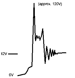
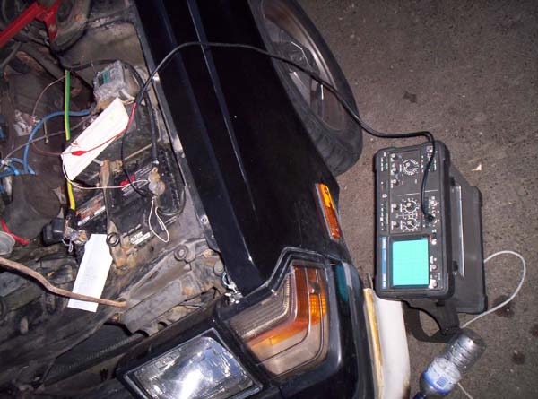
The implementation phase began by examining the voltage signal produced by the ignition coil using an oscilloscope. An oscilloscope is a device that lets you examine voltage produced by a signal as a function of time (picture a graph where the X-axis represents time, and the Y-axis represents Voltage). A great writeup on oscilloscopes can be found here, and here is a picture of ours. With the vehicle running, the oscilloscope produced a waveform much like the following diagram:
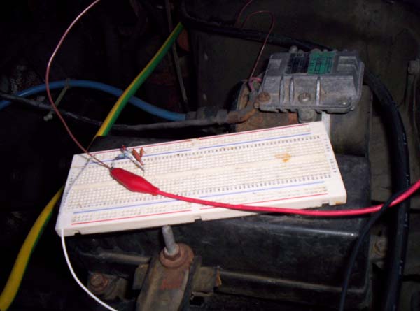
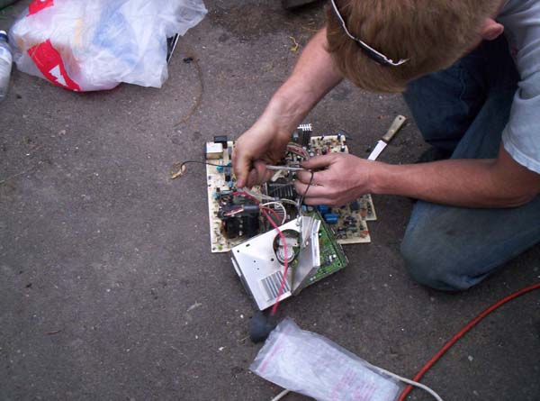
Most of the components we were to use we would acquire from boards lying around. We connected a wire from the low-voltage side of the coil to a breadboard, and then wired a 1 Mega-Ohm (1 million Ohms) resistor in series. We found that no current was passing through the resistor, the resistance was too high. We stepped down to 100 Kilo-Ohms (100 thousand Ohms) and the signal was carrying through with a great deal less amperage, however the voltage signal looked the same (an image of us observing this).
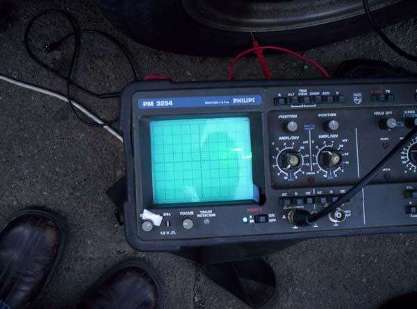
After the resistor, we wired a 5.5V zener in parallel with the output and grounded it (consult the blue coloured section of the above electrical diagram). This worked exactly as planned, and the voltage was regulated between 0 and 5 Volts. The voltage wave seemed very square, however we still had the foreseeable problem with the resonance causing additional undesired voltage transitions that the TTL 4-Bit Counter would pick up. Bryan realized that perhaps a single capacitor would clean up what was the left of the resonance. Through a trial and error process, using different capacitors we arrived at the following waveform on the oscilloscope:
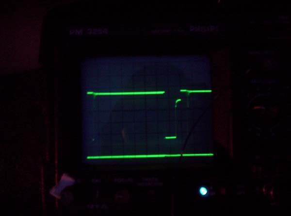
The bottom line is a reference line we used (at 0V) and each dark line along the Y-axis represents 1V (it is difficult to see but the voltage peaks at 5.5V). Here is an image of the circuitry at this step (you can also see the coil right behind it, the cylinder with the blue spark plug cable coming from it in the upper image):