High-Level Discussion on the Software Approach
The purpose of the software system is presently to acquire, process, and display data.
Acquiry
As stated in previous weeks, the sensors are all connected to a 4-Bit Signal Bus. A particular sensor is activated to provide its data to the bus VIA a Tri-State Buffer (it is sent a TTL high, or 1, to its Output Enable pins). The data received from the bus comes through the parallel port to the 4 input pins used. Each time the bus is polled, two important values are stored: the value on the bus, and the time of the polling. After this polling of the data, the Tri-State Buffer for the sensor is deselected. Next, the 4-Bit Counter for the particular sensor is reset. It is very important that acquiry - this polling process - occurs frequently enough to acquire all sensor pulses.
Processing
Calculating outputs to display to the user (Speed, Engine RPM) from the value given in a single poll alone will be very inaccurate (the value from a single poll ranges between 0 and 15). Therefore, a collection of values from polling are used to calculate an accurate value. Considering a collection of polls (that occured within the last one second for example) provides more accurate output with much finer granularity, even presently when all poll values are weighted uniformly.
Each sensor has its own unique formula due to certain details concerning what the signal for each sensor represents. For example, the number of pulses given by the Hall Effect Sensor for the Tachometer reading over a given amount of time is exactly twice the number of revolutions of the engine's crankshaft over that same amount of time. A detail such as this makes the formula to determine this sensor's final output distinct.
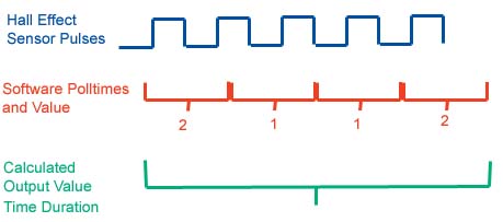
The following image simplifies the idea of the system and will aid in some mathematical discussion:
The Hall Effect Sensor Pulses come through to the 4-Bit Counter and 1 is counted for each leading edge of a pulse (a vertical edge that moves from TTL low to TTL high). These pulses do not come at a fixed rate - rather it is variable in response to the object the sensor is monitoring. It is the variable duration of the pulses for the Hall Effect Sensor that leads to various output values.
The pulses are polled at a theoretical fixed rate, call this duration t. This duration is constant, and is marked in red in the above diagram. Note the variance between values with each poll (the alternation between 1 and 2, the number of leading edges from the pulse sensor). This gives an intuitive explanation as to why using a single poll to produce final output (even though the poll is timestamped) is a bad idea. So a collection of these polls is used (also based on time, as polls expire). This duration is marked in green in the above diagram, call it d.
The polls (both values and timestamps) are stored in an array. Call this array P. The size of this array is directly dependent upon the time that polls are considered, as well as the frequency of the polls. The formula to determine the size of the array P for a particular sensor, Psize, is:
Psize=d/t
For example, if there were 20 polls per second, then t=0.05. If the time for polls considered in a calculation, d, is 1 second, then d=1.0. Therefore, the size of the array P for this sensor is:
Psize=d/t=1.0/0.05=20
Each poll in array P contains both a value and timestamp. Denote the value of the poll at element i P(i)value and the timestamp P(i)time. The formula to calculate the output for this particular sensor is (assuming P is 1-indexed):
OutputTachometer=(The sum of all P(i)value, i=1..Psize, where P(i)time>CurrentTime-d)/d*60/2
Note that the final *60/2 are particulars to the Hall Effect Sensor. Since the unit of measure is seconds, and the desired output is revolutions per minute, 60 is multiplied. And since 2 pulses represent a single revolution, it is divided by 2.
Display
For effective display, this application implicitly required a graphics package. The selection was a collection of libraries known as Allegro, which provide many low level routines for graphic display. These libraries are compatible with DJGPP and other DOS-based 32-bit compilers.
From the Human-Computer Interaction perspective, since the user is likely driving the vehicle while operating the software, the output data should be able to be read very easily. It is for this reason that displays have tended more toward gauges in appearance, in an analog style, versus digital seven-segment displays or other numeric styles of display. An analog-style appearance makes the output easily discernable to a user compared to numeric display, especially when in the user's peripheral vision.
Presently implemented is a Tachometer display containing both the traditional-style gauge as well as a separate numeric display giving the exact value being displayed.
Software Subsystem Class Architecture
The following class declarations are the foundation for the software at this stage:
class Poll {

  public:
  Poll();
  void setTimestamp(double timestamp);
  void setReading(unsigned char reading);
  double getTimestamp();
  unsigned char getReading();

  private:
  double timestamp;
  unsigned char reading;

};

class ParallelPortIO {

  public:
  ParallelPortIO();
  void setSimulated(bool simulated);
  bool getSimulated();
  Poll *obtainPolls(int busaddress);
  void addPoll(int whichsensor, double timestamp, unsigned char reading);
  int pollSensor(int whichsensor);

  private:
  //number of samples held for each sensor dynamically determined
  Poll *inputsequence[NUMINPUTSENSORS];
  int beginindex[NUMINPUTSENSORS];
  bool simulated;

};

class GUI {
  public:
  GUI();
  void update(ParallelPortIO *ppio);
  void incrementPoll();

  private:
  double lastupdate;
  int currentscreen;
  int lastpolls;
  int numpolls;
  double lastsecond;

  BITMAP *doublebuffer;
  BITMAP *logo;
  BITMAP *optionmenu;
  BITMAP *tachometer;
  BITMAP *numbers[10];
  BITMAP *needle;
  BITMAP *whiteline;
  BITMAP *smallredline;
  BITMAP *bigredline;
  BITMAP *rpmx1000;

  void drawTachometer(ParallelPortIO *ppio);
};
Poll is a class that is used as a data structure to store the results of a sensor poll. The private attribute reading contains the value found during the poll, this is the value on the bus after selecting the sensor. It is of type unsigned char, and always ranges between 0 and 15. The private attribute timestamp contains the time in seconds that the poll was made (relative to when the program began execution). The granularity of this value is relative to the number of clock ticks that occur per second on the target machine (typically this value is 100). This class contains trivial methods to set and get these private attributes.
ParallelPortIO is a class used to handle interfacing with the Parallel Port, which is the source of communication for this project. The methods getSimulated and setSimulated are get and set methods for the private attribute simulated. This boolean variable determines if this class's routines should actually interface with the Parallel Port to obtain ports, or simulate these polls. obtainPolls is a method used by class GUI to obtain the array of polls so that a value can be displayed. addPoll is a method used solely by the class responsible for simulating polls, otherwise the method pollSensor is used - this is the important method that accepts the sensor to acquire a poll for as a parameter, and contains the hardware communication code. The other private attributes of this class store all of the polling data. inputsequence is a 2-dimensional array, one dimension accounting for each sensor, and the other dimension accounting for a sequence of polls. This array holds elements of class Poll. They are indexed into this array VIA a separate one-dimensional array called beginindex, with elements for each sensor, to determine the appropriate index to insert the poll into. After each insertion, the beginindex for the sensor is incremented, and when the end of a line of the array for a sensor is reached, the beginindex for that sensor wraps back to the 0th element of the array (the array is 0-indexed).
The class GUI is responsible for displaying data in an appropriate manner. Its methods contain the code that are responsible for producing graphics, and taking a series of Poll objects and calculating an appropriate output value for the user. The fundamental method for this class is update and this routine is called constantly within the main loop of the program. This class determines when it necessary to update the graphical interface within the method, it stores the time of each update in a private attribute called lastupdate. It also contains keyboard interfacing routines so that user can select which screens, data, etc they want. setCurrentScreen is a method that sets what should be displayed by the GUI (for example, the Tachometer, Speedometer, etc.) The class calls the appropriate private method such as drawTachometer to display and update polling for the particular output desired by the user.
An additional class was implemented to simulate the sensor inputs. The class declaration is as follows:
class Simulator {

  public:
  Simulator();
  void update(ParallelPortIO *ppio);

  private:
  int state;
  float rpm;
  float speed;
  int gear;
  int curpulses;
  double eventtimestamp;
  float missedlastpoll;

};
This class is responsible for simulating the values obtained by polling the hardware. To simulate normal driving, it acts as a Finite State Machine with transitions between states of accelerating in 1st gear through the gears all the way to 5th gear, and then finally decelerating, and then reiterating this process again and again. Here is a diagram of the FSM:
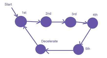
The private attributes contain the data relevant to the simulated data, the state represents the current node the simulator is in the FSM. The condition for transition to increment gear is that a private attribute rpm exceeds 3500. After each transition it is set to 1500. Within each gear state, over time this value is incremented. At the final gear, 5th, the transition is to Decelerate. At decelerate, the transition is back to 1st when rpm is below 800. The concept of having realistic values (an accurate simulation) is less significant in this application as the purpose of the simulator is to ensure proper class interaction in a way similar to hardware interaction, and to evaluate the performance of the display.