Tachometer Signal Conditioner Module Planning:
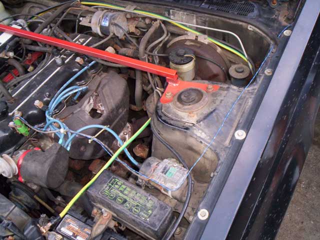
It was later realized that there was an alternate (and much simpler) signal to tap into for the Tachometer pulses - the Hall Effect Sensor. There are a couple important advantages to taking the signal from this sensor than from the Ignition Coil as done in previous weeks. First, the voltage wave produced by this sensor is much closer in appearance to the final conditioned wave that we are after resulting in simpler conditioning circuitry. Secondly, there is considerably less current passing through this sensor - making it safer to work with.
What is a Hall Effect Sensor and how does it work? An introduction to the Hall Effect can be found here. The idea behind it is that when there is a magnetic field and a current that flows through a conductive material, a voltage is produced perpendicular to the direction of the current. This voltage is called the Hall Voltage.
How does this apply to the project? Inside the vehicle, the Hall Effect Sensor exists to determine the time at which the ignition coil should be fired. The significance of Hall Effect Sensors in vehicles is gone into great depths here. Knowing the time at which the ignition coil is to be fired by using the Hall Effect Sensor provides the input signal that will be used to determine revolutions of the crankshaft.
What does this actually look like? The following image conveys the idea.
As the distributor spins the points of the "star" (which is made of conductive metal) has an effect on the coiled wire that consists of the Hall Effect Sensor. As a point moves closer and then farther from the sensor, it disrupts the magnetic field that passes through the coil. This produces a very small change in voltage relative to the ground. The voltage wave produced would theoretically appear something like this:
This voltage wave signal (in particular the positive half) will be used as the signal source.
Speed Sensor Signal Conditioner Module Planning:
The speed sensor in a vehicle gives some very important information to the gauges within the dashboard. In actuality, the speed sensor creates a pulse each time a certain distance has been travelled (meaning it is obviously used for the odometer and tripometer) but it is also used for the speedometer (the pulses "push" the needle of the speedometer to the appropriate angle on the face of the gauge).
In the given vehicle, a 1983 Toyota Celica GT, the speed sensor is essentially a switch that alternates between on and off states. In addition, particular to this vehicle the switch has a transition from off to on 1274 times for every kilometer travelled. This value was given on panelling within the dashboard, as well as in the Toyota Celica manual.
The plan for the speed sensor is simply to attach a line to it and condition the signal to the appropriate voltage and current. Since the mechanism behind the speed sensor is a switch, the voltage wave produced by it is already square. Therefore, a minimal amount of electrical components will be required to do this.
Implementation of Tachometer and Speed Sensor Signal Conditioner Modules:
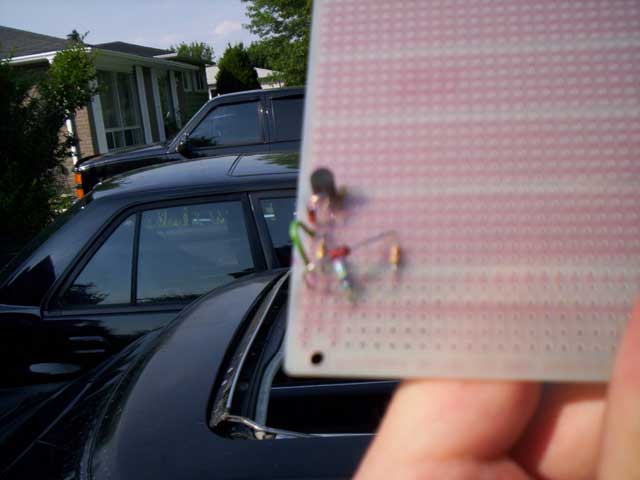
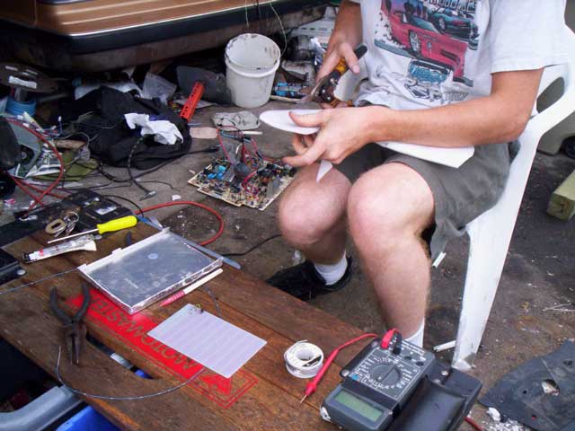
We began the implementation phase with a prototyping board. It is similar to a breadboard but the back surface has the metal connections exposed for soldering. Circuitry for both the Tachometer and Speed Sensor Signal Conditioner Modules will be built onto this board.
Adding the components onto the board piece by piece, the prototyping board finally looked like this. Here are the following equivalent circuitry diagrams for both conditioner modules, as well as their respective sensor inputs:
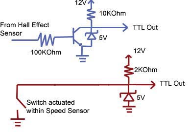
So how does the above circuit in blue utilizing the Hall Effect Sensor work? Square wave pulses are generated by the Hall Effect Sensor. The circuit added as a "parasite" line should not interfere much with the signal of the sensor otherwise ignition problems can arise, so a resistor with great resistance (100 Kilo-Ohms) is used to isolate a signal from the line. The signal across the resistor has extremely low current. The next component in the circuit is a transistor. In general, transistors are used for taking a signal with low current, and turning it into a signal with high current. A great page which introduces the basic concepts behind transistors can be found here.
So when the Hall Effect Sensor creates a pulse, it actuates the "Base" part of the transistor, and current flows from the "Collector" (the upper part of the transistor) through to the "Emitter" (the line with an arrow on the lower part of the transistor). Since the current flows through the Emitter to ground, it will not flow through TTL Out, and so TTL Out has a voltage of 0. When the Base of the transistor has no current, the Collector does not flow to the Emitter, and instead flows through TTL Out. The 5V Zener is connected along the line so that any excess voltages are dropped down to 5V (therefore TTL Out in this state reads 5 Volts).
How does the second above circuit in red utilizing the speed sensor work? This circuit is actually quite simple. Within the Speed Sensor, there is a switch that alternates been on and off (or open and closed) positions. When closed, the current flows from the 12V lead through the 2 Kilo-Ohm resistor (to reduce current) across the switch to ground. At this time, TTL Out will be 0V. When the switch is open, the current instead flows through TTL Out - note again that excess voltages are dropped down to 5V due to the Zener - and TTL Out then reads 5V.
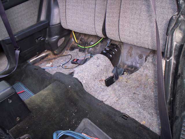
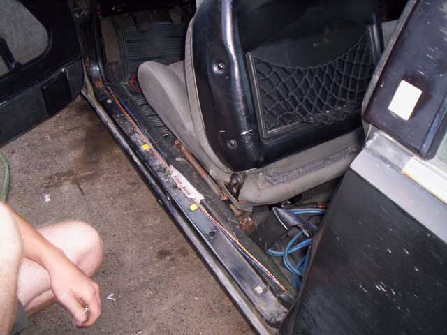
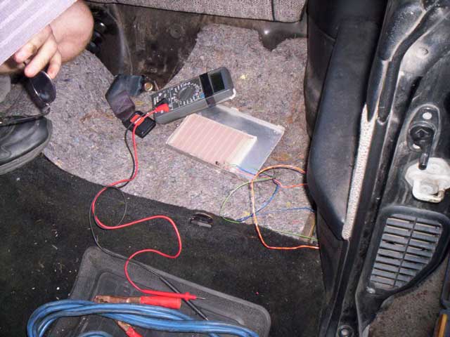
It was decided to fabricate a housing for the circuitry and keep it mounted beneath the back seat behind the driver. The Hall Sensor lead (blue wire connected to green cylinder-shaped object) and other leads were connected, and lead through the panelling along the floor. Finally, with the leads connected, the Signal Conditioner Modules in their housing looks like this. A digital multimeter was used to test that connections were secure, and an oscilloscope was used to test that the circuits were conditioning the signals properly.