 |
 |
 |
 |
 |
 |
 |
 |
 |
 |
 |
 |
 |
 |
 |
 |
 |
 |
 |
 |
 |
 |
 |
 |
 |
 |
 |
 |
 |
|
 58 58
Other values move the system onto a
|
 |
|
result in a number of successful steps but eventually fall.
|
 |
|
successful walking limit cycle. Some walks don't fall despite seemingly chaotic motion.
|
 |
|
|
|
 |
|
The first results we show use the base PCG of Figure 3.7 and the stance hip perturbations and the stance hip perturbations
|
 |
|
described in Section 3.6.
|
The RVs consist of the components of the up vector, as illustrated in
|
 |
|
Figure 3.12 (c).
|
Torso servoing is not applied.
|
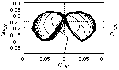
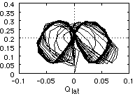
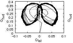
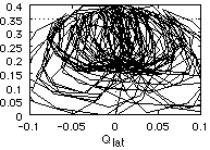
Figure 4.2 shows a representative set of RV shows a representative set of RV
|
 |
|
trajectories corresponding to
|
successful
|
walking
|
trials
|
of
|
60
|
steps.
|
These
|
curves
|
are
|
the
|
 |
|
experimentally-based equivalents of the idealized cyclic trajectories shown earlier, such as those of
|
 |
|
Figure 3.3.
chaotic.
|
In three of the plots, a clear limit cycle emerges.
|
In the fourth, the trajectory is
|
 |
|

|

|
 |
|
(a) F-L sampling, Qd = [.25,0] = [.25,0]
|
(b) L-F sampling, Qd = [.2,0] = [.2,0]
|
 |
|

|

|
 |
|
(c) SP sampling, Qd = [.3,0] = [.3,0]
|
(d) L-F sampling, Qd = [.35,0] = [.35,0]
|
 |
|
Figure  4.2 4.2 - -
|
 Continuous-time Continuous-time
diagrams
|
up-vector
|
RV
|
component
|
phase
|
 |

 1
2
3
4
5
6
7
8
9
10
11
12
13
14
15
16
17
18
19
20
21
22
23
24
25
26
27
28
29
30
31
32
33
34
35
36
37
38
39
40
41
42
43
44
45
46
47
48
49
50
51
52
53
54
55
56
57
58
59
60
61
62
63
64
65
66
67
68
69
70
71
72
73
74
75
76
77
78
79
80
81
82
83
84
85
86
87
88
89
90
91
92
93
94
95
96
97
98
99
100
101
102
103
104
105
106
107
108
109
110
111
112
113
114
115
116
117
118
119
120
121
122
123
124
125
126
127
128
129
130
131
132
133
134
135
1
2
3
4
5
6
7
8
9
10
11
12
13
14
15
16
17
18
19
20
21
22
23
24
25
26
27
28
29
30
31
32
33
34
35
36
37
38
39
40
41
42
43
44
45
46
47
48
49
50
51
52
53
54
55
56
57
58
59
60
61
62
63
64
65
66
67
68
69
70
71
72
73
74
75
76
77
78
79
80
81
82
83
84
85
86
87
88
89
90
91
92
93
94
95
96
97
98
99
100
101
102
103
104
105
106
107
108
109
110
111
112
113
114
115
116
117
118
119
120
121
122
123
124
125
126
127
128
129
130
131
132
133
134
135


