An Automated Rigging System for Facial Animation
I wrote this thesis for my Masters degree, which I obtained from the Program of Computer Graphics at Cornell University.
The idea behind this project was to create a system to process facial 3D scans of real people and generate an animatable character.
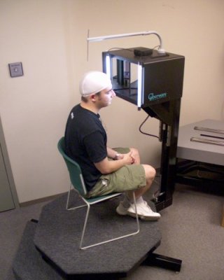
Technical details: The facial scans were obtained with a Cyberware 3030/RGB Color 3D Scanhead mounted on a Portrait Scanner motion platform.
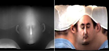
The scanner is shown in action below. It generates two images: a radial depth map and a radial texture map. These can be combined into a 3D model. Note that the scanner cannot capture certain parts of the face very well, so there are holes under the chin and eyebrow, and the back of the ear appears stretched and glued to the rest of the head.
 |
 |
 |
Unfortunately, the 3D models produced by the scanner have too many samples to be animated at interactive rates. Therefore, the models must be decimated before they are animated. This fact is one of the foundations of our system.
My facial animation system has three major subsystems:
Each one of these is easy to understand, but there are lots of details, so I'll just give an overview here. If you are interested in more details, you are welcome to read selected chapters of my thesis.
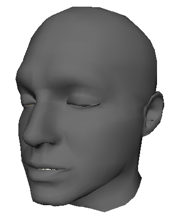
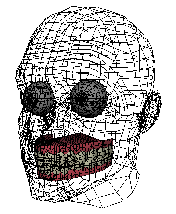
The generic face model I built for this project is named Murphy, shown below. The eyes, teeth, and tongue are modeled as separate meshes, not shown. The connectivity of Murphy's mesh is also shown. The yellow edges are used for adding creases to the forehead and eyes when the skin compresses. The blue edges are built radially in order to generate the curved creases around the mouth when a person smiles and "crows feet" at the eyes.
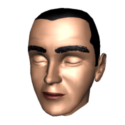
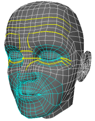
The texture is very basic. Note that there is no model for the eyebrows. These are present in the texture only.
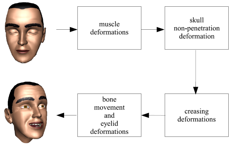
The rig itself can be broken down into four stages pictured in the diagram above.
The first stage of deformers in Murphy's rig is the muscle model. This is a geometric deformation model that simulates the action of the main expression muscles in the face. I chose a muscle-based parametrization for two reasons: 1) the goal is to use Murphy as a template for animating real human faces, and 2) all humans share the same musculature and interpret expression by the actions of these muscles.
Broadly generalizing, there are three types of muscles of expression in the face: sheet muscles, orbital muscles, and linear muscles. Linear muscles are the easiest to describe, as they intuitively connect one point on the skull to a corresponding point on the skin (for example, the zygomatic major, or smiling muscle). Sheet muscles connect a broad area of the skull to a broad area of the skin, (frontalis muscle, or eyebrow raiser). Finally, orbital muscles contract in a circular fashion. There are exactly three of these in the face: one around each eye (orbicularis oculi, or eyelid closer) and one around the mouth (orbicularis oris, lip puckerer).
In my system, all of these muscles are modeled with a linear muscle model. A sheet muscle can be easily modeled by coupled linear muscles in close proximity. For the orbital muscles, I simply chose one or two linear directions which best mimic the visible effects these muscles have on the skin. A comparison of the human musculature and the muscles I implemented is shown below.
Those users familiar with Maya will notice the muscle lines are drawn as joints. This is really only a visual guide--the actual muscle is described by an anchor point and a scaling direction. There is no "skinning" in the muscle model.
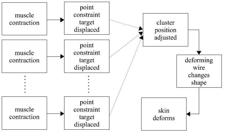
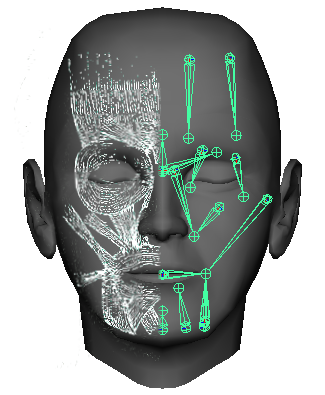
Each muscle has a region of influence about the face, and there are a few skin regions in the face where many muscles attach and pull in different directions. Therefore, the effect of all the muscle activations must be somehow averaged. My muscle model does exactly that. The actual muscle deformation chain is pictured above, and works as follows.
We consider small patches of skin where the muscles attach (or have influence), and for each muscle, we place a locator (a point) associated with that muscle. When the muscle activates (is scaled down), each of these locators moves as if the skin patch were only attached to that muscle. When many muscles are activated concurrently, we have as many targets for the positions of skin patch points. The final position of the skin patch point is thus an average of the target positions weighted by user-defined weights.
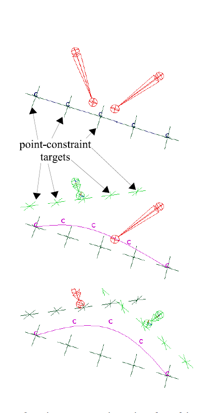
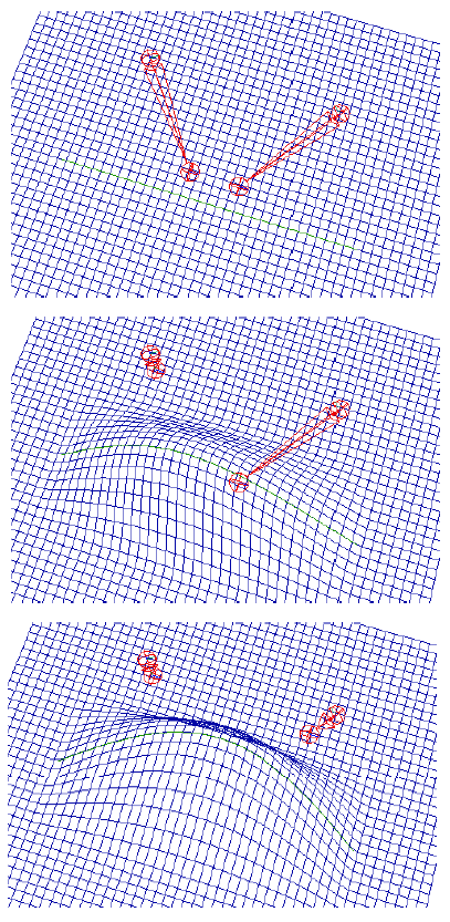
The muscles attach to the small patches of skin at curves (polylines) on the surface, and the points we constrained above correspond to the vertices of these polylines. Each of these curves is the driving curve for a Wire deformer. This is the deformer that actually moves the skin. The whole procedure is also pictured in the diagrams below. The letters "C" represent the curve control points, and the crosses are the target positions.
As you can see from the above description, the muscle model does not have a concept of bones! Thus, using it by itself unrealistically deforms the regions of the eyes, denting the skull. Here we perform a simple correction step. We find all the points that are inside the skull boundary and push them out to the surface. Here, "inside" is measured in the direction the face is pointing toward--this is the same direction in which we push the offending points.
Creases in the face are an important cue for facial expression. If we could find a person with raised eyebrows, but no creases in the forehead, we would immediately find something awkward even if we would not be able to pin point the problem.
In my system, I use special creasing deformers to generate creases along the forehead and at the corners of the eyes. These deformers simply push strategically placed vertices on the mesh into the face (see above.)
Finally, these deformations are responsible for gross motions of the head about the neck and for jaw and eyelid rotations. There is also a deformer that prevents penetration of the eyelids into the eye.
There are a few deformations not mentioned in the diagram above, which correspond to motion of the eyes and the tongue. These are generated with standard point constraints and smooth skinning.
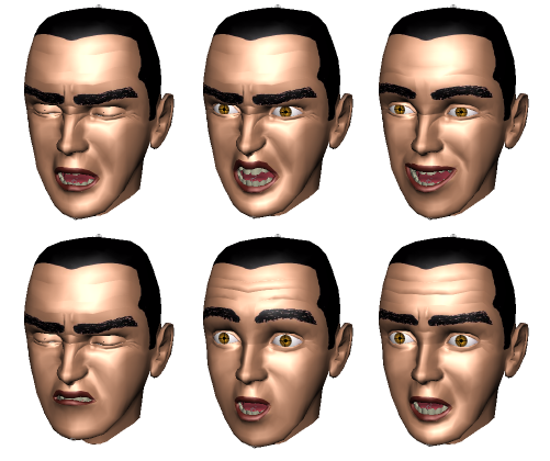
This rig works well. The image below shows Murphy demonstrating the six universal expressions using the rig described above.
The most important part about this rig is the fact that its construction is parametrized on the connectivity of the mesh describing Murphy. Therefore, if we deform this mesh to look like a different character, we can, at the push of a button, rebuild the rig and animate the new character immediately. There are, of course, some limitations on the classes of deformations allowed. The most important constraint is that the mapping retains the semantics of the face. In other words, the mapping must map the tip of the nose to the tip of the nose, and points on the cheek to points on the cheek. Otherwise, rebuilding the rig will produce unexpected results.
The deformation algorithm was modeled after W. K. Jeong et al., Automatic Generation of Subdivision Surface Head Models from Point Cloud Data, GI 2002 (available here). A diagram for the main steps is shown below.
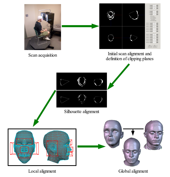
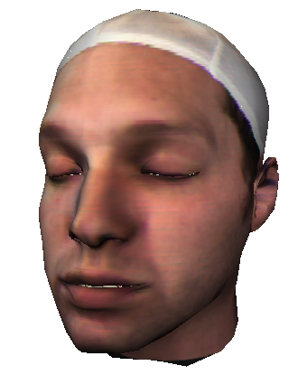
The scan acquisition simply runs the Cyberware scanner on the actor. Note that in order to avoid dealing with the errors of scanned hair, I had the actors wear a swimming cap. Also, I asked the actors to close their eyes during the scan, since in my system their eyes are substituted by my own model.
After scan acquisition, the user roughly aligns the silhouettes of the scan and the reference mesh using a GUI tool. This provides an initial guess for an automated minimizer, which runs next. The minimizer uses graphics hardware to find the rigid transformation that minimizes the silhouette difference between the scan and the reference mesh. The GUI tool also provides the ability to define clipping planes in order to eliminate regions of the scan producing large error from the automated computation. Typically, the top of the head and the whole of the chin and neck are removed from this computation.
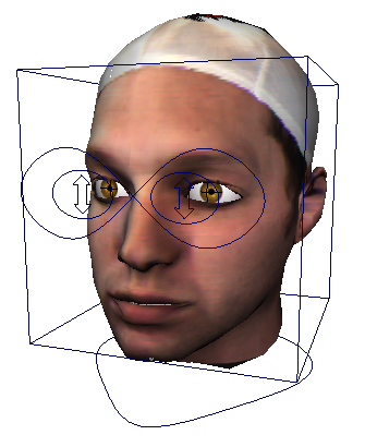
Following the silhouette alignment, a local alignment step runs which tries to fit important facial features together. Jeong's system uses four boxes, and mine uses five. We fit the nose, mouth, eyes, and ears. There are a number of technical details here which I'll ignore. However, note that this step is extremely important in creating the semantic correspondence between the scan points and the reference mesh. The minimization in this step also computes rigid transformations, one per box, for the region contained in the box. These transformation are then blended outside of the box.
Finally, the global alignment step computes the warp for the reference mesh to minimize the distance from it to the scan points. Again, there are many details here, I'll just mention a few. I developed a new constraint, called a barycentric constraint, which prevents points inside the nose from projecting outside of the scan. It also allows the sliver triangles in the creasing regions to retain their shape, instead of having the edges criss-cross due to the minimization. Care must also be taken around the ears, as the distance minimization will tend to push the hidden regions out toward the scan points and also spread out the region where the ear attaches to the head. Finally, there are some constraints to prevent the mouth and eyes from opening.
The whole procedure ran in a few minutes per scan, but, unfortunately, it is not very robust. I did not have the time to implement a better deformation procedure, but in 20/20 hindsight I would have used an RBF deformation model (see, for example, Head shop). These models map given anchor points the reference mesh to anchor points on the scan, labeled by the user. Therefore, the semantic correspondence is ensured. Also, the actual fitting is procedure is simple, as it only involves a solving a linear system of equations.
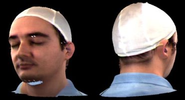
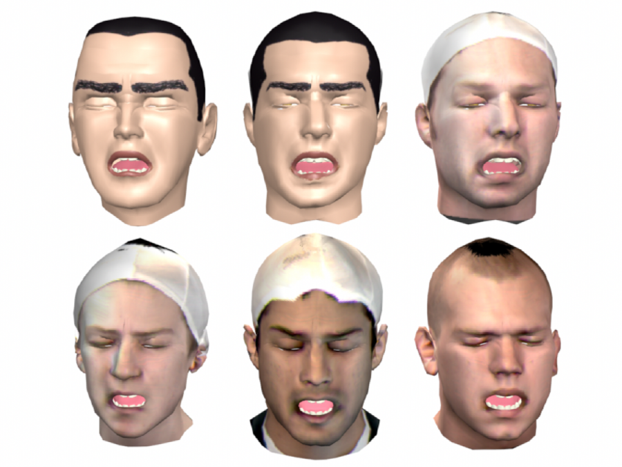
However, the system found good warps for the majority of the scans, as can be seen below. Note the downsampled, low-pass filtered quality of the resulting mesh.
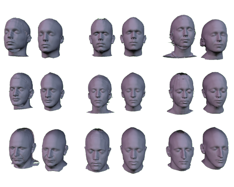
The final step in the system is to rig and animate the new character. The first step here is to select a warped reference mesh. Next, the eye and teeth models must be placed inside the character by the user, since these cannot be placed in the appropriate locations using the connectivity information in the mesh alone. The user also places the texture on the character if desired--typically this texture comes from the facial scan. Finally, with the press of a button, the system runs a script and builds the rig on the character.
Some animation controls for parameters more easily set visually are shown above. However, the muscle controls are not readily available immediately. However, I wrote GUI that easily allows the user to manipulate the new character.
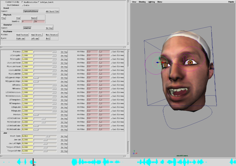
Although not immediately obvious from the image above, there are 3 ways the user can choose to animate the character. There are sliders which use the names of the muscles for those animators who have strong anatomical knowledge. To simplify the interface for those who don't, there is a second tab which groups the muscles into left/right pairs and provides names to the controls which match our intuition for the resulting shape. Finally, there is a third tab with an expression library of predefined shapes for the user to quickly reach a particular effect.
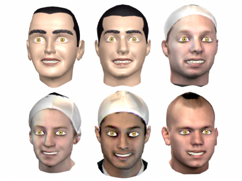
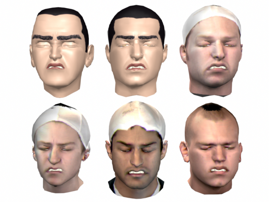
The header image above shows the "fake smile" expression for six characters. Below are the same characters showing the six universal expressions.
Sadness
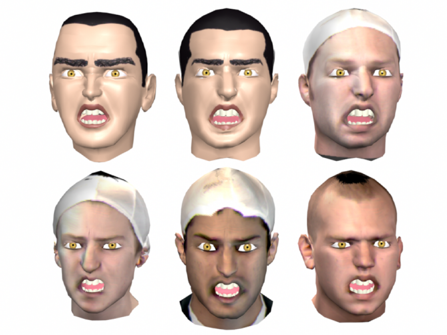
Anger
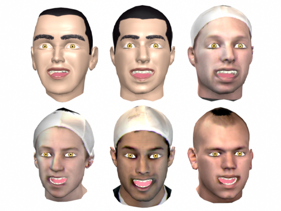
Joy
Disgust
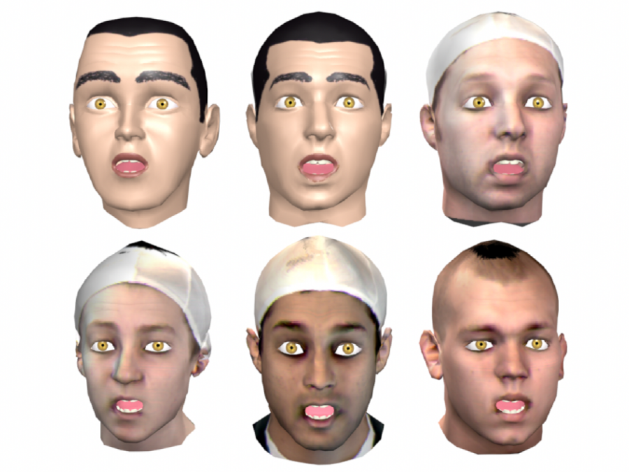
Surprise
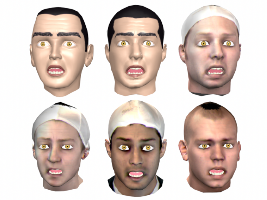
Fear
I was very happy with this work, but in reality it is not quite production ready. As I mentioned before, the weakest link in the system is the warping between the reference mesh and the target facial scan. However, I believe an RBF mapping would greatly improve the robustness of the system and also speed up the scan to rigged character process.
The rig can also be improved by adding orbital muscles, which could be modeled by anchor points that scale down elliptically in a user controlled way. Also, the muscle model can be improved by adding bone contraints directly into the muscle contraction procedure. Finally, we avoided rendering the hair and skin realistically in this work, but we should include these for a full production system.
This model is not limited by the number of different faces it can represent--as long as we can scan the person's face, we can build an animatable model. An advantage over systems based on shape blending is that our model is predictive: we can generate expressions for a new character without having to capture that particular expression in a blend shape database. The expressions are realistic and recognizable, and maps scanned faces to animatable characters well. Therefore, we achieved all the main goals of the project.