 Progressive Radiance Evaluation Progressive Radiance Evaluation
We have developed a progressive refinement algorithm that generates an approximate image quickly, then gradually refines it towards the final result. Our algorithm can reconstruct a high-quality image after evaluating only a small percentage of the pixels. For a typical scene, evaluating only 6 % of the pixels yields an approximate image that is visually hard to distinguish from an image with all the pixels evaluated. At this low sampling rate, previous techniques such as adaptive stochastic sampling suffer from artifacts including heavily jagged edges, missing object parts, and missing high-frequency details.
A key ingredient of our algorithm is the directional coherence map (DCM), a new technique for handling general radiance discontinuities in a progressive ray tracing framework. Essentially an encoding of the directional coherence in image space, the DCM performs well on discontinuities that are usually considered extremely difficult, e.g. those involving non-polygonal geometry or caused by secondary light sources. Incorporating the DCM into a ray tracing system incurs only a negligible amount of additional computation. More importantly, the DCM uses little memory and thus it preserves the strengths of ray tracing systems in dealing with complex scenes.
We have implemented our algorithm on top of RADIANCE. Our enhanced system can produce high-quality images significantly faster than RADIANCE -- sometimes by orders of magnitude. Moreover, when the baseline system becomes less effective as its Monte Carlo components are challenged by difficult lighting configurations, our system will still produce high quality images by redistributing computation to the small percentage of pixels as dictated by the DCM.
The rendering pipeline of our system. The approximate image is available any time, on demand. When all blocks are of the pixel size, the iterative block refinement terminates with the approximate image output as the final image.
 (a)
(a)
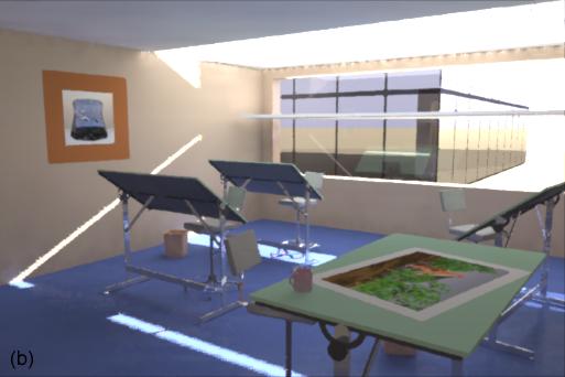 (b)
(b)
 (c)
(c)
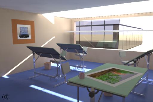 (d)
(d)
Click on the images above to see full-size versions.
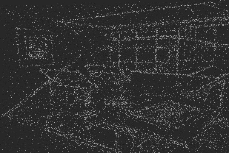
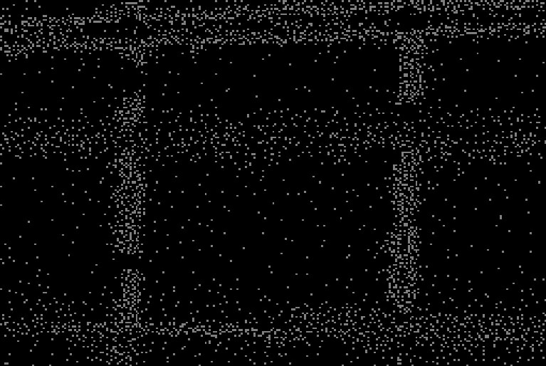
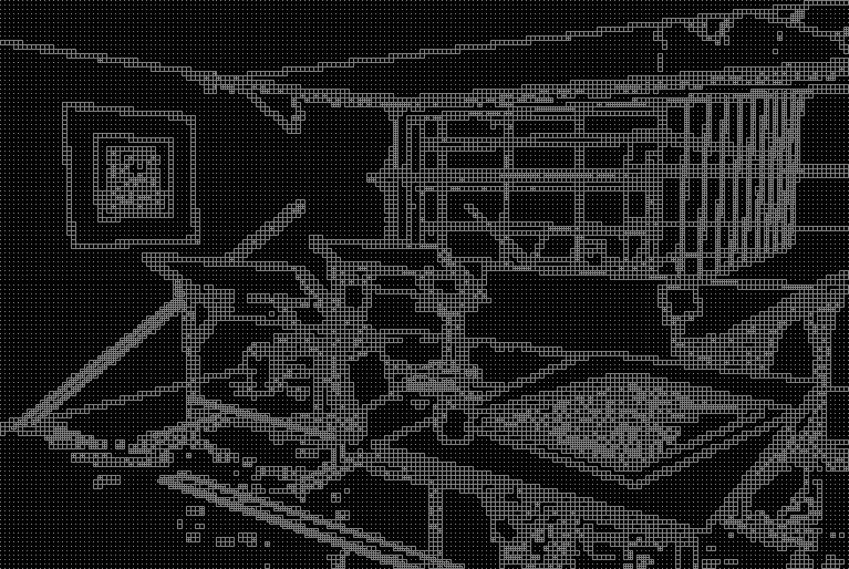
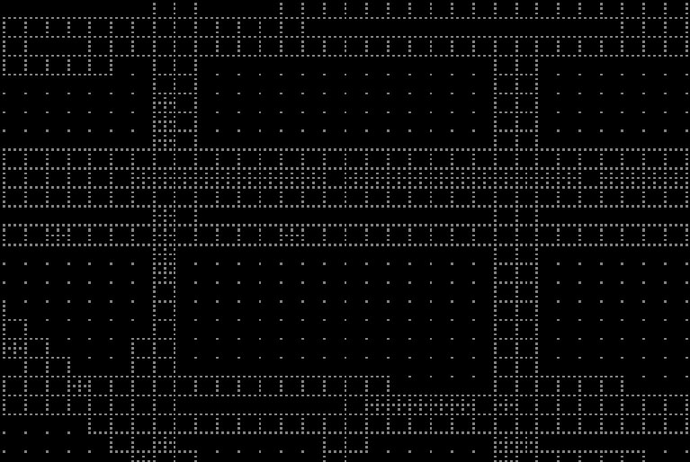
Progressive renderings of an office scene lit by sunlight transferred through a light shelf. (a) The approximate image at the end of the regular subdivision, with 1.6 % evaluated pixels located at the corners of the 8 X 8 blocks in the work image. (b) The approximate image after boundary evaluations for all 8 X 8 edge blocks in the work image, with 5 % of pixels evaluated. (c) The approximate image after evaluating about 6 % of the pixels, whose locations are shown below. (d) The final image as rendered by the baseline RADIANCE system. The scene model was supplied courtesy of Greg W. Larson.
The discontinuity in (a) is considered simple whereas that in (b) is not, because of the corner. The geometry for the least-discrepancy direction is given in (c). In (d) we show the construction of a typical bilinear element. Essentially this construction is a Gouraud interpolation with the scanline rotated to be parallel with the least-discrepancy direction. Note that (d) is a zoomed version of the shaded element in (f). Finally, oriented finite elements are shown in (e) through (h) for four different orientations.
Block simplicity test examples. Case (a) passes both the zero order and first order tests. Case (b) passes the zero order test but not the first order. Case (c) fails both tests. The black and light grey line segments on the block boundary are spans.
The first order test for block simplicity. (a) The tangent direction for the edge passing through x_0 can be estimated from the transition points x_0 and x'_0 on two adjacent layers. (b) To pass the first order test, the line segment [x_0,x_1] (the thin black line) and the tangent directions at the two transition points x_0 and x_1 (the two thick black lines) must be nearly parallel.
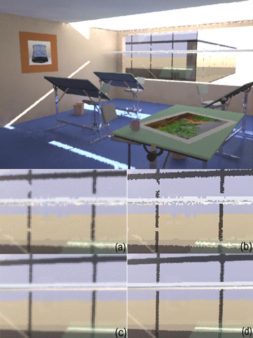
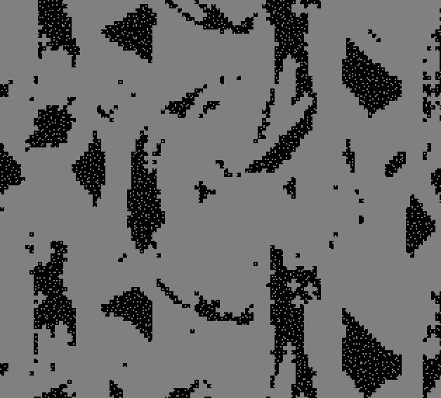
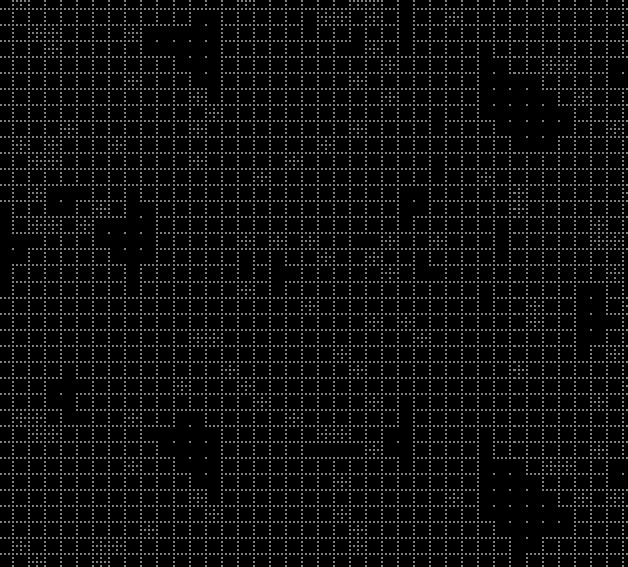
Comparison between the DCM and adaptive stochastic sampling with the office example. The top image, rendered by sampling 6 % of the pixels using Painter's adaptive stochastic sampling technique, should be compared with the 6 % DCM image (progressive rendering series above, c). The bottom image contains four zoomed views of the same region: 6 % Painter image in (a) with its work image in (b), and 6 % DCM image in (c) with its work image in (d). Sampling masks for the top image, images (a) and (b) , the 6 % DCM image, and images (c) and (d) .
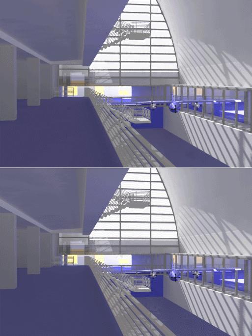
Progressive renderings of a museum scene lit by skylight through the window. Notice the fine shadows cast by the polygonal occluders. The top image is the approximate image after evaluating about 7 % of the pixels. The bottom image is the image rendered by the baseline RADIANCE system. The scene model was provided courtesy of Charles Ehrlich.
 (a)
(a)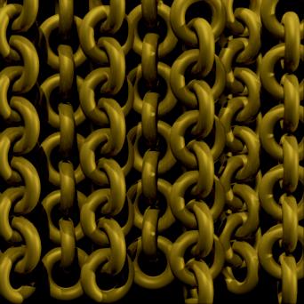 (b)
(b)
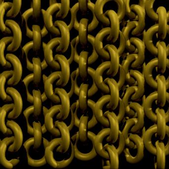
Image (a) is a benchmark image rendered by Rayshade. Image (b) is rendered using the DCM after 10 % of pixels have been evaluated. The main purpose of this experiment is to test the DCM's capability in treating discontinuities that cannot be handled by existing discontinuity algorithms. The scene model was provided courtesy of Stuart Warmink. Sampling masks for a region in image (a) and the same region in images (b).
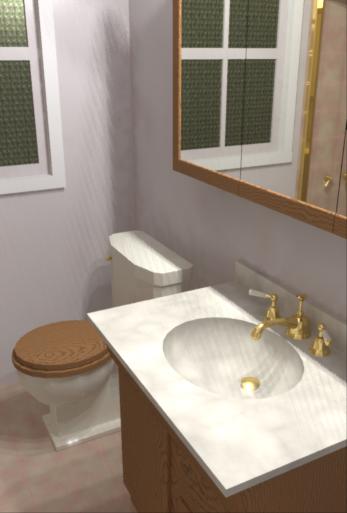
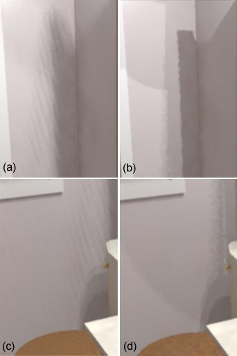
The image on the left is rendered using the baseline RADIANCE system by setting the quality to the highest level available. On the right, (a) and (c) are zoomed views of two regions from the left image. Notice the striping artifacts and missing penumbra boundaries. In (b) and (d), we show zoomed views of the same two regions from an image rendered in less time by our progressive renderer.