1. [10 marks] The digits in a standard seven-segment display are typically displayed like this:
 _         _    _         _    _    _    _    _
| |    |   _|   _|  |_|  |_   |_     |  |_|  |_|
|_|    |  |_    _|    |   _|  |_|    |  |_|   _|
The input to a seven-segment decoder is a four-bit binary number which is between 0 and 9 inclusive (10 through 15 are "don't care" situations), and the output consists of one output wire for each segment of the display.
(a) Show a Karnaugh map for the middle segment (the segment which differs between the 0 and the 8), then deduce a minimal sum-of-products expression, and draw a circuit for it.
(b) Draw a circuit for the bottom-middle segment (Karnaugh map (etc) not required, unless you find it helpful). (This is the segment which is on for all digits except 1, 4, and 7.)
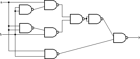
2. [9 marks] You have the following circuit:

This logic diagram was developed for implementation using a technology which has only NAND gates. You are now working with a technology that has only OR and NOT gates. Convert this logic diagram to an algebraic expression, simplify it, and draw a much smaller logic diagram which uses only OR and NOT gates.
3. [5 marks]
(a) Give a possible pin-out for a hypothetical MSI 20-pin chip which multiplies two four-bit numbers, producing an 8-bit product. That is, for inputs A and B, it produces the value A*B (which we could call P, for "product").
| 1 | 20 power |
| 2 | 19 |
| 3 | 18 |
| 4 | 17 |
| 5 | 16 |
| 6 | 15 |
| 7 | 14 |
| 8 | 13 |
| 9 | 12 |
| 10 ground | 11 |
(b) Give any one good reason that a chip series (such as the 74LS series we're using in the CSC258 lab) would never include such a chip. (There are several good answers here.)
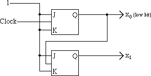
4. [5 marks] Here is a standard two-bit ripple counter:

Draw a two-bit synchronous counter.
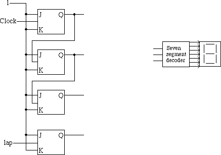
5. [10 marks] Here is a three-bit ripple counter, to be connected to a seven-segment display with a decoder which accepts a three-bit number to be displayed. Draw connecting circuitry to provide a "lap" button which when pressed, freezes the display on the screen but the counter keeps counting. When the "lap" button is pressed again, the display jumps to the current value of the counter and continues counting. Thus this "lap" button toggles a JK flip-flop, which is also shown. (Hint: use non-master-slave, non-clocked latches for the three data bits.) (Note: this question is somewhat difficult. Don't let it take all your exam time.)

6. [10 marks] A vending machine accepts only nickels (5¢ coins) and dimes (10¢ coins). The maximum price of any item is 10¢.
Design a circuit to implement part of the price checking for this machine. Your circuit will get input data from other parts of the vending machine. Each time a nickel is deposited, the "nickel" input line goes to 1 for one clock cycle. Similarly there is a "dime" input line. Once a purchase is made, a "purchase" input line is held at 1 for one clock cycle and should cause your circuit to forget the deposited money.
Use two master-slave flip-flops (of any kind you wish). One represents the user having deposited at least 5¢ (a nickel or a dime) and the other represents the user having deposited at least 10¢ (which could be a dime or two nickels). Don't worry about clearing the flip-flops upon power-on. There is more circuitry to be attached to these two data values, but you don't have to design that for this exam question.
7. [10 marks] Here is the standard recursive factorial function in several programming languages; read it in the one you know. (I believe that everyone here knows at least one of these programming languages; if not, please ask me to write this function out for you in some other programming language you know.)
C or Java (or C++):
int f(int x)
{
    if (x > 1)
        return x * f(x-1);
    else
        return 1;
}
|
Turing:
function f(x:int) : int
    if x > 1 then
        result x * f(x-1)
    else
        result 1
    end if
end f
|
Pascal:
function f(x:integer) : integer;
  begin
    if (x > 1) then
        f := x * f(x-1)
    else
        f := 1
  end;
|
Fortran:
INTEGER FUNCTION F(X) INTEGER X F=1 IF(X.GT.1) F=X*F(X-1) RETURN END |
Write a recursive factorial function in PDP-11 assembly language using this algorithm. The argument is pushed on the stack; the result is returned in R0.
Do not assemble your program; leave it in symbolic form.
Note added in 2002: This question tested students' ability both to write subroutines and subroutine calls, in one little subroutine...
8. [15 marks] What will be the values of all four condition codes after performing each of the following four-bit additions? One example answer is provided.
Example question:
 1111 (-1)
+1111 (-1)
 ----
 1110 (-2)
Example answer: N=1; Z=0; V=0; C=1
Exam questions:
 0111 (7)
+0111 (7)
 ----
 1110 (-2)


 1010 (-6)
+0111 (7)
 ----
 0001 (1)


 1000 (-8)
+1000 (-8)
 ----
 0000 (0)
9. [8 marks]
The ASCII character code for space is 408; the code for 'h' is 1508; and the code for 'i' is 1518. Write a program in PDP-11 assembly language (machine language) which puts "hi" in the top left of the screen (memory locations 160000 and 160001) and clears the rest of the screen (by putting spaces there).
Do not assemble your program; leave it in symbolic form.
solution
But as noted above, this concerns material not discussed this
term!
10. [8 marks] The following sequence of assignment statements, using a bitwise xor:
P := P XOR Q
Q := P XOR Q
P := P XOR Q
exchanges the values of P and Q. That is, the final value of P (after the above three assignments) is equal to the initial value of Q (before the above three assignments), and the final value of Q is equal to the initial value of P. (If you don't believe me, prove it to yourself after the exam...)
Using our simple one-bus CPU architecture (see appendix B to this exam), which includes an XOR control line to the ALU, write microcode which uses the above algorithm to exchange the contents of R0 and R1.
11. [10 marks] In a pipelined CPU, suppose that we have the following two consecutive instructions:
        ADD R1, R2
        MOV R2, R3
In this case, during the execution of the second instruction we need
operand forwarding
to take place so that the value moved into R3 is the new value of
R2 rather than the old value of R2. This was discussed in class when
discussing RISC CPUs.
Draw appropriate circuitry to provide the value to be moved in a MOV instruction. This value, then, will sometimes be from the register and will sometimes be from the ALU result. Assume an instruction format which has the opcode (MOV or ADD) in bits 15 through 8, a source register number in bits 7 through 4, and a target register number in bits 3 through 0. The current instruction is in a register IR0 and the previous instruction is in a register IR1. Operand forwarding occurs when the new instruction's source register is equal to the old instruction's target register; when the register numbers are equal, the value is the value from the result bus rather than the value of the source register.
Use high-level components in your logic diagram where useful. For example, you could use a four-bit comparator which takes two four-bit numbers and outputs one bit which says whether they are equal. And you will probably have a register file whose input is the four-bit register number (e.g. 0100 for R4) and whose output is the 16 bits of data in that register.
You must specify what input lines you need, then draw a circuit whose output lines are the sixteen-bit value which should be connected to the bus while the target register's "in" line is set.
End of exam.
Total marks: 100