Team members:
James McCrae - Laptop interfacing and software subsystem
Bryan Stuurman - Mechanical and electrical hardware
Supervisor:
Objective:
The development of a computer system which is physically connected to the sensors of the vehicle's motor to acquire signals. Also, the development of a software solution to acquiring and processing the data from the connection. Finally, an open exploration into the relevance and potential for this system - and Computer Science in automotive technology.
Current Status:
Schedule of Deliverables:
| June 4/04 | Project Commencement |
| June 15/04 | Custom Signal Conditioner Modules constructed and installed in vehicle |
| June 18/04 | Preliminary software subsystem design complete (basic interface, simulating sensor inputs, and preliminary signal processing for tach signal and vehicle speed displays) |
| June 25/04 | Signal bus constructed and installed in vehicle |
| June 30/04 | Laptop computer installed in vehicle and parallel port connected to signal bus |
| June 30/04 | Hardware communication modules for software subsystem prepared for on-board testing |
| July 7/04 | Worked out particulars/difficulties with intercommunication of hardware/software subsystems |
| July 21/04 | Finalized signal processing functionalities of software subsystem and error detection features |
Finally, dependent on time constraints and project requirements, acquire additional signals, and add or extend features.
Technical Overview:
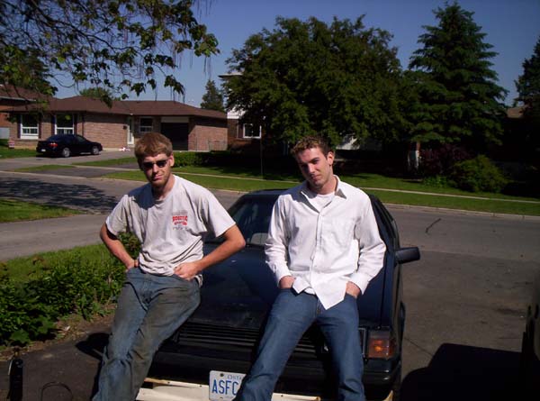
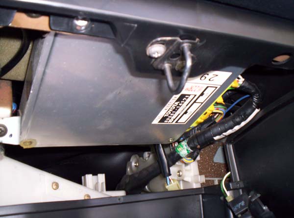
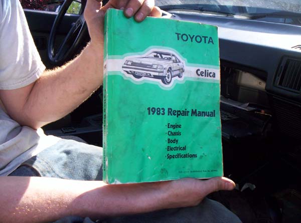
The selected vehicle is a 1983 Toyota Celica, equipped with a 2.4L 4 cylinder reciprocating gasoline combustion engine. The engine is controlled via an analog computer, which monitors up to 7 sensors to determine the proper air-fuel ratio for the specific driving circumstance. Spark timing is separately controlled via a mechano-vaccum advancing system completely isolated from the Engine Control Unit (ECU).
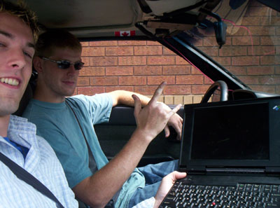
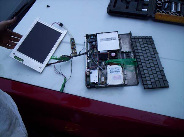
The computer selected is a Commodore laptop, model ANC-4S25. It has a 486 33MHz DX processor (overclocked to 40MHz), Chips 65520 VGA video controller, 640KB base memory and 7424KB extended memory (8MB RAM total), Toshiba HDD2339 250MB Hard Drive, 1.44MB 3.5" disk drive, parallel port (hardware address 0x378) and serial port.
The choice of the vehicle and computer system were severely limited by availability of test equipment, however, these platforms offer an exciting challenge in interfacing, and allow exploration of Computer Science solutions to signal acquisition and processing.
Project Plan:
Stage 1
In stage one, our goal is to install the entire laptop computer into the car, and interface its parallel port to the vehicle's sensors. The four TTL input lines on the parallel port will be treated as a bus. 4-bit counters driven by conditioned signals from important sensors can be selectively attached to the bus and polled for the sensor's "count". Such a system allows for up to 6 input sensors with 4-bit resolution. The 12 TTL outputs on the parallel port will serve as data select/reset pairs for the six input devices.
The parallel port is a TTL I/O port which is completely software driven. This allows for expected polling rates of up to a 1% maximum of the CPU clock speed (assuming a C implementation, in a monotasking enviroment). A polling rate of at least 400kHz is then expected of the test computer, which is more than adequate considering the reduction of overhead given by the 4-bit counters. The net effect is a 400*16 kHz, or 6.4MHz sample rate. Clearly, such a sample rate is not required, but the speed of data acquisition leaves CPU overhead and thus potential for computation in real time. This hardware configuration ensures that signals can be acquired faster than they are given.
Fundamental sensors selected for observation will be Tachometer and Speed. The Tachometer signal is a "messy" digital signal with about the same levels as 12v CMOS signalling. This signal will need to be inverted, dropped to a TTL level and conditioned with a small high pass filter to eliminate transients. The Speed signal is somewhat sinusoidal at variable voltage and frequency. A conditioner module will be built to detect the zero-crossings of the sinusoid and convert them to TTL logic pulses (since there are two pulses for each wave, the acquired value will have to be divided by two - to be addressed by the software subsystem).
The following diagram presents the modular components of the electrical hardware system:
Stage 2
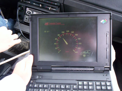
Software for the assembled hardware platform from stage one will consist of MS-DOS as the operating system, with an implementation built in either DJGPP (MS-DOS port of GNU C/C++ compiler) or Borland Turbo C/C++. Initial code will be designed simply to test I/O routines and ensure the data from the vehicle sensors is correctly acquired. This can be determined by ensuring the data displayed by the computer is coincident with the readings presented on the dashboard of the vehicle.
Upon diagnosing and addressing all hardware issues, the software subsystem will have successfully acquired and displayed signal information.
Stage 3
This stage provides an open exploration into the possibilities available with the system implementation. Research and analysis will be conducted, and solutions will be proposed to the following issues:
References:
"Interfacing the IBM PC Parallel Printer Port"
http://www.lvr.com/files/ibmlpt.txt
"Programming the parallel port"
http://www.gmonline.demon.co.uk/cscene/CS4/CS4-02.html
"How Car Computers Work"
http://auto.howstuffworks.com/car-computer.htm
"1983 Celica Maintenance Manual"
Toyota Motor Corp.
"DJGPP"
http://www.delorie.com/djgpp/