 |
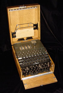 |
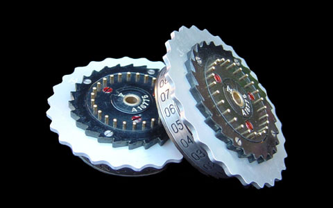
| Two Enigma rotors. | A complete Enigma Machine. |
Modeling Assignment: Enigma Machine
Inspiration/Source Material
For this assignment we had to construct a "functional digital object". Given that this is a Geometric Modeling course, I wanted to create an object which was visually interesting and a challenge to model, as well as having an interesting function. I had recently looked into Enigma Machines out of curiosity, and this seemed like the perfect opportunity to see how much I actually understood about how they work.
Information about Enigma Machines came in two forms: how they machine looked, and how it actually worked. Fortunately, there are a lot of helpful pictures of every part of the machines available online, like these:
|
|
|
| Two Enigma rotors. | A complete Enigma Machine. |
There are also many websites with information about how the Enigma works, its history, and how it was solved:
Tony Sale's excellent Enigma site, describing exactly how the machines work
W1TP Online Enigma Machine Museum has a ton of pictures
How the Enigma Machine (Basically) Works
The Enigma Machine enciphers a message with a basic substitution cipher. That is, every letter is replaced by another letter from the alphabet - for example, A for E, B for Z, and so on. The Enigma Machine expands on this concept in two interesting ways: first, it accomplishes this substitution by a series of electrical connections that are hidden from the user. Second, these connections are placed in a set of rotors which can rotate, changing the electrical connections and thus the substitution cipher. This rotation is what made the Enigma code so difficult to crack - it meant that every letter in a message was enciphered using a different substitution cipher, because the rotors would rotate after every letter was entered.
Modeling
I chose to model the machine with polygons because I'm most familiar with polygon modeling, and I wanted to recreate the mechanism of the machine as precisely as possible. Polygon modeling gave me the control that NURBS surfaces wouldn't. However, I encountered the downsides of polygon modeling as well, which is discussed below. I modeled the machine in 3D Studio MAX because I am more familiar with MAX's tools and workflow, but in the end its operations are completely analogous to Maya.
Rotors|
|
|
The splines for the rotor, arranged in the order they will be assembled in. |
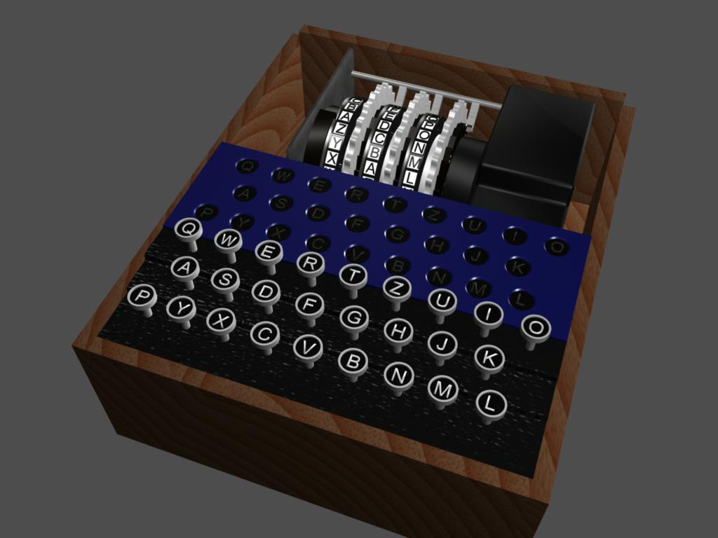
The Machine
Some aspects of the remainder of the machine were again created by lofting
a 2D spline of their cross-section. Some other parts, such as the keys or
the box containing the machine, were made from polygon primitives like cylinders
and boxes that were manually tweaked.
The Problem
The downside to polygon models is, of course, the hard edges. Since
real objects don't have hard edges, I manually bevelled/smoothed the edges of
some objects. The keys presented another problem - their polygon
silhouette was clearly visible. I couldn't bevel these edges, and regular
smoothing resulted in a bizarre-looking result. In this case, I used some
of the things I'd learned about subdivision surfaces (for my upcoming paper
presentation) and created a subdivision surface which kept the sharp edges of
the original key. Subdividing this created a key which was smoother
radially but kept the hard edges I wanted.
 |
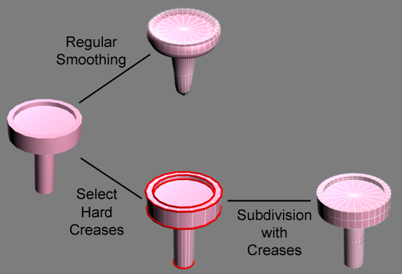 |
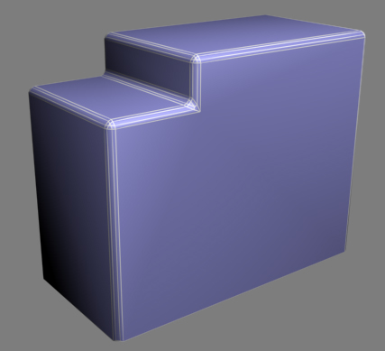
| This boxy structure was smoothed along the edges (wireframe is superimposed). | The original key (on the left) has clearly visible polygonal edges. Smoothing causes problems, but subdivision with specified creases creates a smoother model with the desired hard edges. |
Shading
To keep things simple, all shaders were made from scratch using only procedural textures, instead of images. Most are simple Phong or Blinn shaders to achieve a plastic or metal appearance, and a few have procedural colour maps (for brushed metals) or bump maps (for example, the bumpy black plastic cover over the rotors).
Animation
In the end, I decided to control the machine by MEL script instead of interactively (e.g from an expression). A MEL command takes a string as input and based on the current rotor state animates the keys, rotor motion, and (after the encipherment process) the light corresponding to the enciphered letter output. Each rotor has a lookup table corresponding to its substitution cipher, and these are chained together to actually encipher the input just like the actual machine did. The rotors are pushed by components of the machine called pawls, which act like an odometer - after every full rotation of the right hand rotor, the middle rotor rotates one step, and so on. Depending on the rotor state, pawl motion is copied from the appropriate entry in a "pawl library" of every possible pawl motion.
Results/Conclusion
Renderings:
 |
Full Enigma Machine, with rotor cover removed to show internal detail. |
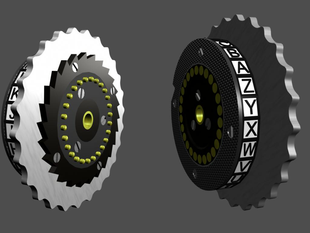 |
Rotor detail. |
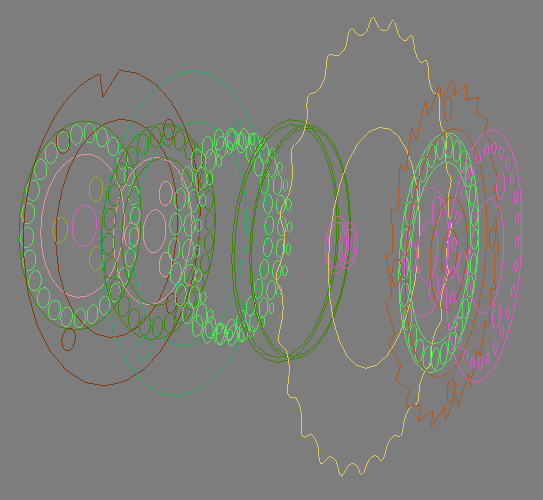
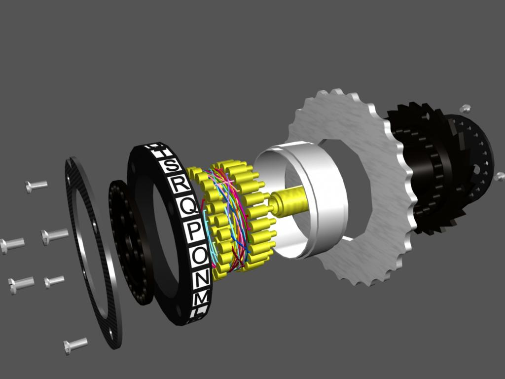 |
Exploded view of a rotor, showing every component. Note the coloured wires which connect the 26 input and output pins - these wire connections effect the substitution for each rotor. |
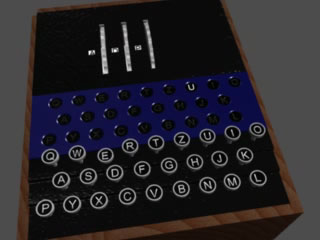 |
Encipherment In this animation, the text "ENIGMA" is entered. The output ciphertext "UWXAQV" flashes in the corresponding lights, in sequence. |
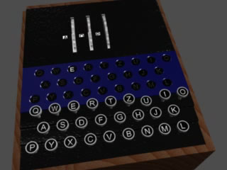 |
Decipherment One property of the Enigma code was that it was reciprocal - this made decipherment simple. In this animation, the input text is the ciphertext from the previous example - "UWXAQV". Because the starting rotor state is the same as the encipherment, the output is the original text, "ENIGMA". |
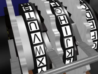 |
Rotor Details This animation shows the rotor motion from the previous animations, including the pawls pushing the rotors. The first rotor moves into its "knock-over position", which advances the second rotor on the next letter. This advances the second rotor to its own knock-over position, which moves all three rotors on the letter after that. After that, with no rotors in their knock-over position, only the first rotor rotates. |
Conclusions
One interesting aspect of the real Enigma Machine is a phenomenon called "double-stepping", where the middle rotor advance on two successive keypresses. I couldn't understand how this process occurred from the internet sources, so I decided to leave out that functionality of the machine. However, when testing the machine I discovered that pieces were intersecting each other - it was impossible for the machine to not double-step! Now that I could see a working machine, I was able to understand the double-stepping and add the functionality easily.
Finally, I've learned my lesson about polygon modelling - never again! The sharp edges are especially troublesome, because real objects don't have them. Using subdivision surfaces would allow more accurate modeling, especially with metal objects that should have a slight reflection along their (slightly bevelled) edges - this doesn't occur with sharp polygonal objects. Lesson learned for next time.
Source files
enigma.zip - a compressed version of the (very large) Maya 4.5 file in ASCII format, with all the geometry and shaders.
enigma.mel - in order to run the machine, you will have to load this MEL file and call the enigmaMachine.enterString() function with the desired input.